 How To's
|
Joined: Jan 2005
Posts: 6,307 Likes: 3
Worn Saddle
|
OP

Worn Saddle
Joined: Jan 2005
Posts: 6,307 Likes: 3 |
To be honest, I don't remember who sent me this, but if they remind me, I will post the correct credit where it's due, Edited: Kudos to BrianT Inexpensive AI RemovalHey folks, just got done removing the noose from around my Beastie's neck, and only cost me about $10 (for 2 M12x1.25 Drain Plugs Part Number 65214, $2.49 each, 1 Tube Copper Anti-seize $2.98, and 1 box generic 3/16" Vacuum Port Plugs Part Number 47391, $1.99, all from Advance Auto, but probably the same at AutoZone or Napa, or any other chain auto parts place) I downloaded the instructions from this site (link below), and made 2 minor mods. Some tips: 1. Unbolt the Reed Valve after loosening the 2 clamps on the rubber hoses going from the Air Injector tubes to the Reed Valve. Once you take out the two Reed Valve mounting screws, you can slide it forward, and pop it easily out of the ends of the two rubber hoses. 2. I did have to destroy the two compression clamps that hold graphite filled compression fitting (between the short black elbow and chrome injector nozzles) to get the fitting and black elbows off, only because I didn't have a 13mm Open end that would fit down into the opening to loosen them. If you have such a small 13mm open end, then you won't have to do this. Either way, new clamps are very cheap if I want to reinstall later. 3. I cut about 1/4" of the tip of the M12x1.25 drain plugs off (it was just a non-threaded guide section anyway, no threads removed) to make them the same length as the threaded section of the Air Injector Nozzles, just to be on the safe side. 4. Instead of removing the big 3/4" air hose from the Air Intake box to the Reed Valve, I just bent over the last 2", and tie wrapped it shut. Very simple, very effective. If I happen to need to reinstall the system, the hose is still there, or if I stumble across just the right size bung to fill that hole in the airbox, I'll replace the clamped off hose, either way, no one is the wiser from looking at the bike. And the drain plug bolts look like they actually belong, they look like they are fastening the cylinder jugs to the crankcase. Total time to do this was 2 hours 21 minutes, but that included time to run to 2 different parts stores to get the drain plugs (naturally one store was short one on their inventory), run by Wendy's to grab lunch, and babysit my two little boys at the same time!!! So real work time was probably 1 hour easy, and not real challenging at all. Maybe some day I’ll go back an buy the cool bolts with the Union Jack engraved in the head, maybe not. Will post photos. Oh, by the way, why didn't someone tell me this thing had spark plugs, found 'em tucked in behind the AI Injector tubes!!! And all this time, I thought this thing was a diesel!!!! Hmmm!! OH, and I haven't touched the screws yet, that is next, but the popping is almost completely gone, what little I hear is when I stand over the bike with my head next to the end of the pipes, and gun it! Oh, and the instruction (thanks to Jenks!!!!!) were very straightforward, very easy to follow.
Last edited by moe; 04/05/2012 11:19 AM.
|
|
|
Re: More How To's
|
Joined: Jan 2005
Posts: 2,362
Oil Expert
|
|
Oil Expert
Joined: Jan 2005
Posts: 2,362 |
how-to's on... - the bike watch and a light for it - non-standard driving lights - relocating front turn signals below driving lights - installing an aftermarket alarm - building an LED taillight - hiding the handlebar wiring - mounting aftermarket horns ... plus others as I add them. Matt
|
|
|
Headlight aiming
|
Joined: Jan 2005
Posts: 4,056 Likes: 78
Loquacious
|
|
Loquacious
Joined: Jan 2005
Posts: 4,056 Likes: 78 |
Handy link for headlight aiming from Bonnyusa.
|
|
|
Valve Adjustments
|
Joined: Jan 2005
Posts: 18,825
"Lighten up, Francis."
|
|
"Lighten up, Francis."
Joined: Jan 2005
Posts: 18,825 |
Gathering info on the procedure: Tools/Parts RequiredMicrometer with .001mm resolution Metric Feeler Gauges Torque Wrench that measures Nm and goes below 8Nm Misc metric sockets, wrenches, T-30 Torx bit/socket (you might need more than one - some of the bolts can be tough to loosen and you might break one or two bits) Tool set, wrench and locking pins T3880330, price ranges $44-75 (optional? some have used nails to secure the sprocket tensioners) Parts RequiredNew cam cover gasket (1) T1260900 Cam cover sealing washers (4) T1260209 Crush washer for oil feed tube (2) 3550042-T0301 Oil feed tube o-ring (1) T3600077 Oil feed tube banjo bolts (optional, but they snap very easily so if you're a klutz like me, order a couple) T1211456 Shims, $6-11 each (you won't know what you need until you get deep in the process) - Dinqua's shim calculator (download) - Yamaha V-Max shims are the same diameter, 25mm (in case you don't have a Triumph dealership close) - If you've got the time, post your shim needs in the Classifieds forum and see if other members have the shims you need (see notes, below) Factory InfoValve Clearances in Factory Manual Intake: 0.15mm-0.20mmExhaust: 0.25mm-0.30mmFactory Adjustment Interval: 12,000mi Torque Specs from the ManualCamshaft cover to cylinder head bolds: 10NmCamshaft bearing caps to head bolts: 10Nm (these are fragile, too - if you break one they are M6x40 1.00 pitch) Camshaft oil feed pipe to bearing cap bolts: 8Nm (these banjo bolts are VERY FRAGILE so BE CAREFUL) Fuel tank mounting bolts: 19NmFront seat to mudguard fixing: 26NmRear seat to mudguard fixing: 10NmThe ProcedureHere's the 'Readers Digest' version of the work involved. (Thanks Greybeard) 1. Remove the battery cover and disconnect the battery. 2. Remove the seat(s). (to get at the tank bolt) 3. Remove the fuel tank. 4. Remove the cam cover. 5. Turn the engine 2 full revolutions, stopping each 1/4 turn to check the valves and noting the clearance. 6. Remove the cams if the valves need adjusting. 7. Remove the shims as needed. 8. Inspect the shims for wear and measure the true thickness. 9. Calculate the required thickness. 10. Install the new shims. 11. Reinstall the cams. 12. Turn the engine over by 1/4's again to make sure of the adjustment.** 13. Reassemble the bike. 14. Start it up and warm up the engine, checking for noise and leaks.** 15. Take a test ride.** ** Anything wrong at these points means doing it all over again, usually for free. Misc NotesTight valves will burn in short order. Very loose valves will eventually pound the cam faces and valve stems out of shape. (Greybeard) Before you run out and buy all new shims, run the numbers with Dinqua's calculator and see if you reuse some of the old ones in other locations. Up until now I've never thought of this, but those of us who don't do our own valve adjustments should ask for our old shims back when taking the bike to a dealer to get this done. I know I was charged something like $7.xx for each shim they replaced, and they kept the ones they took out. You have every right to ask for the old shims if you're being charged for new ones. If we get enough people getting their old shims back, we can send them them off to whoever(Pat?), and it wouldn't take long before we'd have a ample supply of every size shim needed. Then Pat, or whoever, could send out the correct size shims to those who need them. (SalMaglie) Exhaust vs. Intake CamshaftIf you mix up the camshafts, you will damage your valves. Do not underestimate how fragile all these bits are. There is an easy way to tell the difference and it isn't by markings on the sprockets. In the middle of the camshaft there is a raised boss that is either smooth (exhaust) or has a groove cast into it (intake). There is a picture in the manual; I'll try to scan and upload it. Thread Links
Last edited by FriarJohn; 02/28/2012 8:14 PM.
|
|
|
Barnette Clutch installation
|
Joined: Jan 2005
Posts: 12,877
Should be Riding
|
|
Should be Riding
Joined: Jan 2005
Posts: 12,877 |
Last edited by moe; 05/16/2011 10:51 AM.
Benny
Black & Silver '02
Too many mods to list
Not enough miles ridden
|
|
|
Trimming the T100 sprocket cover to fit
|
Joined: Jan 2005
Posts: 12,877
Should be Riding
|
|
Should be Riding
Joined: Jan 2005
Posts: 12,877 |
This trimming is necessary because the cover will hit the frame of the bike on the lower-rearmost corner. A small half inch notch allows it to clear the frame and sit flat. From LimeyD: Before... 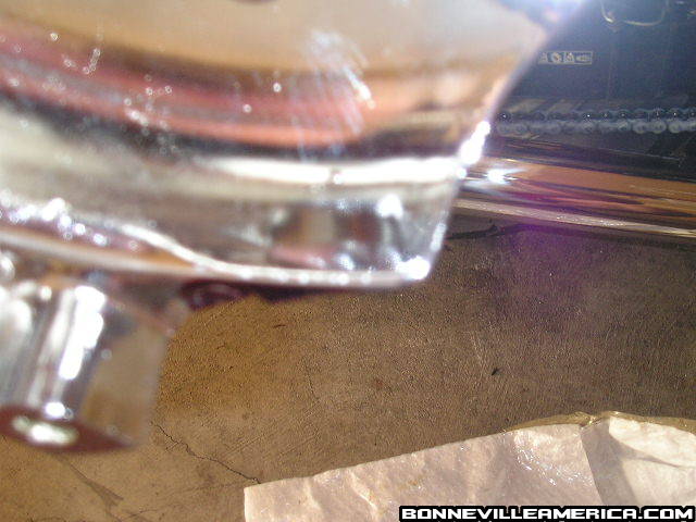 After... 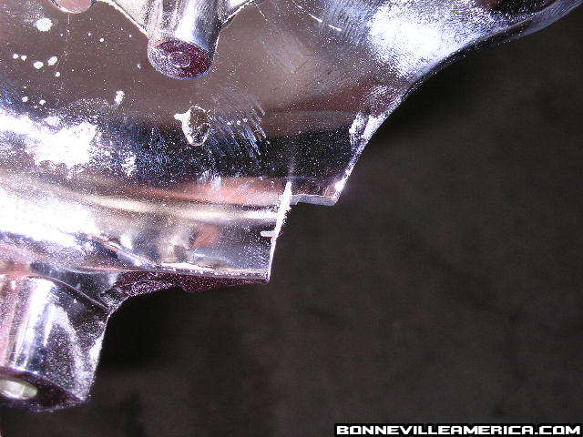
Last edited by bonnyusa; 09/25/2007 5:10 PM.
|
|
|
Freak Alternative - Drilling bottom of Airbox
|
Joined: Jan 2005
Posts: 6,307 Likes: 3
Worn Saddle
|
|
OP
Worn Saddle
Joined: Jan 2005
Posts: 6,307 Likes: 3 |
Remove seat.
Remove snorkle and Air filter.
Remove any more snorkles from inside airbox towards carbs (not in Speedmasters).
Notice the bottom of the airbox has small dimples that hold the air filter in place. DO NOT DRILL THESE OUT, stay inside them as you do the mods.
Stuff some clean rags into the airbox so that plastic particles stay out of the carbs.
Place a piece of wood, we use 3/4" plywood, under the airbox on top of the swingarm as not to chip the swingarm podercoat when you drill through the bottom of the airbox.
Use a hole saw,(smaller than the distance between the oval dimples) or make several smaller holes and then dremel them into a larger hole on the bottom of the airbox, staying inside of the little protrusions that hold the air filter in place. (They are in an oval shape).
Then vacuum all the little pieces of plastic from the inside of the airbox and remove the rags. be sure you get ALL the little pieces. Plastic in the carbs is not a good thing and can easily gum up.
Then as an added precaution, we cut a piece of light guage stainless steel screen door material (or you can even use the plastic stuff too) into a slightly larger oval than the protrusions.
For added safety, and to prevent water entering the bottom of the airbox (which can happen but is extremely rare and only if you ride several miles on water logged roads), you can cut two equal sized pieces of screen material and place a thin piece of foam, like the uni filter foam stuff, between the two layers of screen material. You can also add some of the filter oil to this new bottom filter as well. Then bend the edges of the screen material over so it secures the layers of screen and foam.
Then take the screen piece, be it one or two layers, place it into the bottom of the airbox completely covering the oval dimples.
Cut the bottom out of your air filter but be sure to just cut the inner part out of the bottom, leaving the outer thick edges for grip in the bottom of the airbox.
Firmly press the air filter in place on top of the screen you inserted, it should "POP" a bit as the screen deforms and seats itself between the filter and the airbox.
Be sure the air filter is down far enough to reinstall the top holding plate for the air filter. If not, press it down harder, or use a less rigid stainless screen for the bottom filter assembly.
Replace the top part that holds the air filter in place.
Put the seat back on and ride away.
You will most likely have to rejet after this mod as it allows about 50% more air into your carbs and you will need to balance the gas to match.
This modification is easily reversable by simply replacing the air filter with a new one. The uncut bottom of the filter should plug the hole completely, if not, just cut a small piece of plastic/rubber the same size as the holes and place that under the new air filter, or glue it in for a better seal.
A word to the wise is not necessary. It is the stupid ones who need the advice.
Pat
|
|
|
Ghetto Freak
|
Joined: Jan 2005
Posts: 12,877
Should be Riding
|
|
Should be Riding
Joined: Jan 2005
Posts: 12,877 |
Thanks to Tom (77T140V ) for this one! Cabrini Green - Chicago, Illinois Here's my first draft (and quite possibly final) "talking paper". Bandwidth challenged: Beware it's a little over 2Mb in size, as it's chock-full-o pictures.
Last edited by FriarJohn; 02/01/2011 1:20 AM.
Benny
Black & Silver '02
Too many mods to list
Not enough miles ridden
|
|
|
Seat swaps made easy
|
Joined: Jan 2005
Posts: 4,056 Likes: 78
Loquacious
|
|
Loquacious
Joined: Jan 2005
Posts: 4,056 Likes: 78 |
From Fishercat, a mod that allows you to change from the Touring seat to the solo seat easily and without having to change hardware.
Mod
|
|
|
Triumph luggage rack modification
|
Joined: Jan 2005
Posts: 4,056 Likes: 78
Loquacious
|
|
Loquacious
Joined: Jan 2005
Posts: 4,056 Likes: 78 |
I've finally taken some pix of my lastest project.. What I've done is basically lower the luggage rack approximately 2 inches. Always thinking they were too high up on the bike I finally got brave enough to go for it.. 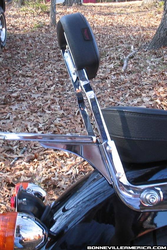 It makes it more functional and lowers the center of gravity of your load just a bit. With the rack installed the rear seat bolt can still be accessed. 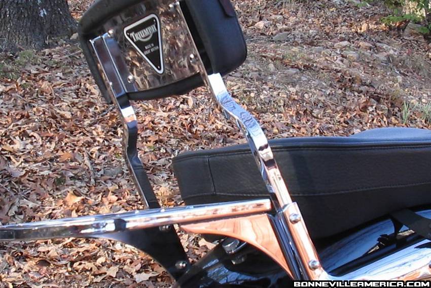 What I did was move the bottom bolt of the luggage rack/sissy bar to the upper hole of the rack and drilled two holes in the support bracket for the rack to accomodate the other two bolts. 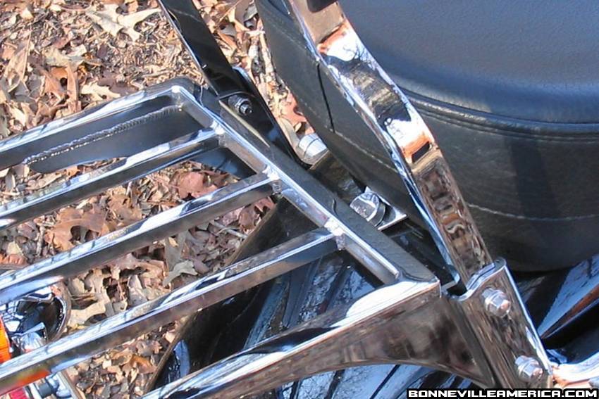 I then cut the lower bolt hole off of the rack support brackets with cutting wheel and smoothed the edges with a dremmel. All in all I'm pleased with the outcome Sorry I didn't take pics of the process but what can I say?.. I was caught up in the moment... 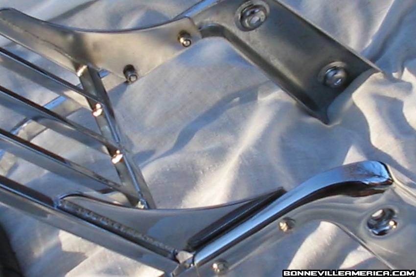 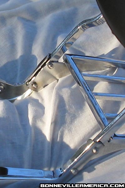
Last edited by FriarJohn; 02/01/2011 1:22 AM.
|
|
|
Simple, cheap driver's backrest
|
Joined: Jan 2005
Posts: 9,223
Big Bore
|
|
Big Bore
Joined: Jan 2005
Posts: 9,223 |
I got the following from member vwone (Dean). All I did was post it for him. Update 12 March 2008: Thanks again to member vwone (Dean) for providing emailing me the photos so this thread's photos could be restored! Dean: "I had a couple of private messages asking how I made my backrest and I thought I would show how I did it. I got the idea from here but could only find one pic and no other details. So here is what I did. 1. You will need a 1/8"x1 1/2"x36" piece of steel from home depot. I think some of us has used aluminum. 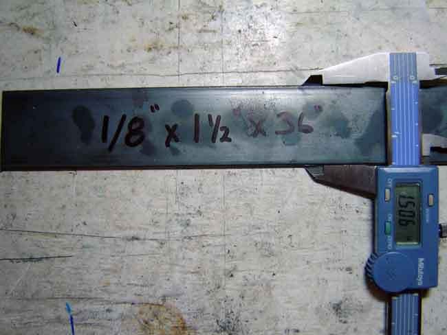 2. You will need to hammer the steel into shape. It should look something like this. 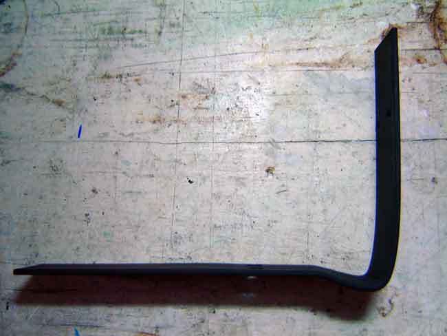 3. Here is what the bottom of the pillion pad looks like. 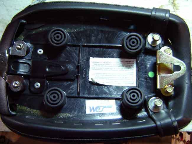 4. Remove the four 10mm bolts. 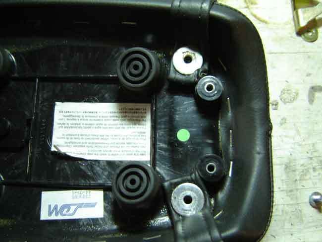 5. Next, you need to make a bracket that will bolt the metal part of the backrest to the two bolts that bolt down the leather strap. [ 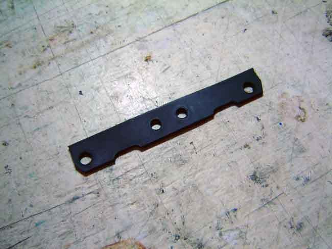 6.Next bolt the bracket to the metal part of the backrest. 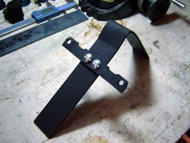 7. Bolt this assembly to the pillion seat. 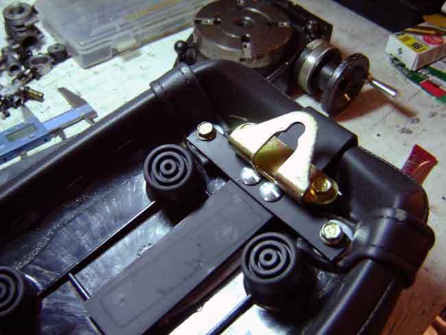 8. It should look like this now. 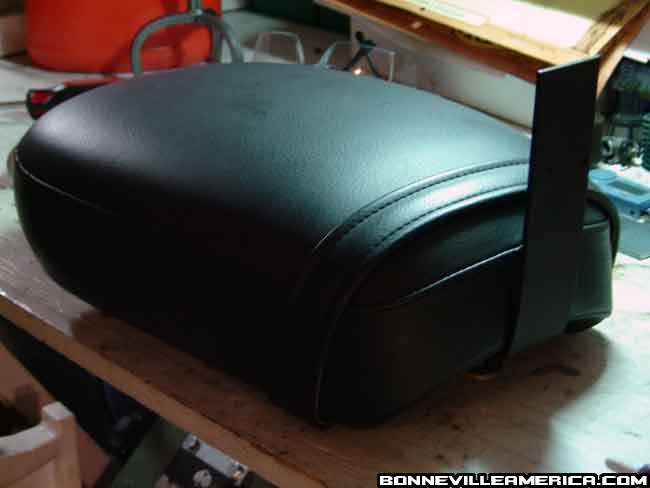 9. Next, I removed the sissy bar pad from the sissy bar. (Photo is still missing for this.) Don't need a picture though. Just unbolt it.  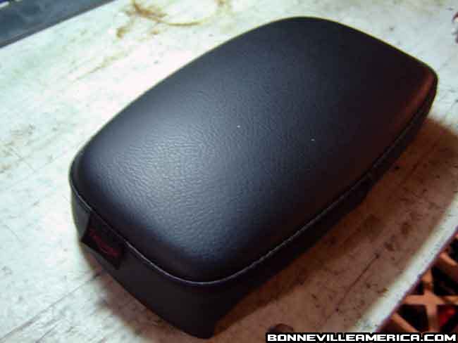 10. I then made a bracket to cover the back of the pad and bolt it to the metal part of the backrest. 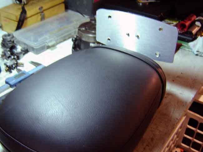 11. Now bolt the pad to the bracket. 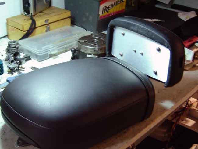 12. This is what it should look like now. 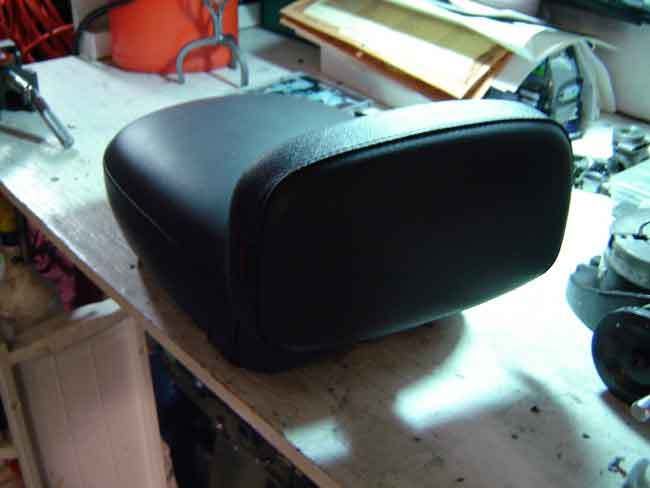 I built this in a couple of evenings and it was not hard. I didn't measure a thing, just eyeballed it and cut. I do have a small machine shop in my garage, but this could be done with a hacksaw and hand drill. It will just take longer. I also left out all of the details like what holes to drill or what taps I used, I assume you will build it differently. If it is needed I can add those details later. Have fun!"
Last edited by moe; 03/12/2008 4:46 PM.
|
|
|
Re: Drag Specialties Tach install
|
Joined: Jan 2005
Posts: 11,120 Likes: 11
Should be Riding
|
|
Should be Riding
Joined: Jan 2005
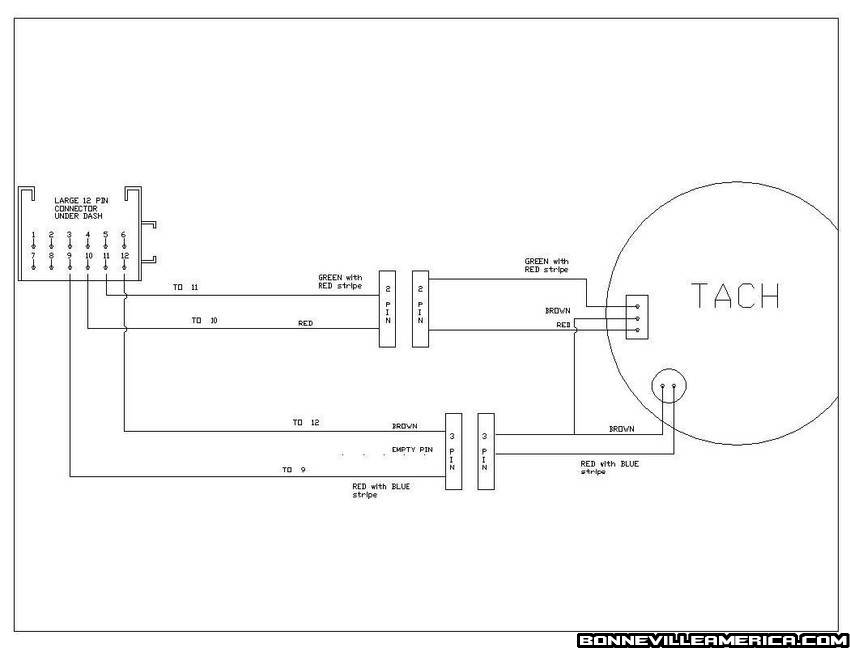
Posts: 11,120 Likes: 11 |
Last edited by FriarJohn; 02/01/2011 1:28 AM.
|
|
|
Fork Oil Changeout / Progressive Spring install
|
Joined: Jan 2005
Posts: 11,120 Likes: 11
Should be Riding
|
|
Should be Riding
Joined: Jan 2005
Posts: 11,120 Likes: 11 |
Step by Step complied from various members contributions: Quote:
Fork Oil Replacement.
Notes:
Top Yoke nut is 30 mm
Fork Caps are 22mm
Each fork takes about 19 oz of oil.
Tips:
*Measure fork oil with a graduated wooden dowel, marked at 160mm, 166mm and 170mm.
*Lube each bottom shroud’s wiper before re-assembly.
*Break loose each fork cap after job completion to burp the air out.
*Removing the tank is optional.
*Compressing the fork after spring removal is easy. This is the fork’s natural state.
*Sometimes the fork’s inner tube will seem to stick when all the way inside the outer tube. Tap gently at the junction or rotate and pull up on the inner tube.
Procedure
Front Wheel Removal
*Break free front axle using 12mm hex on right side of axle. Unscrew it till about 5mm of thread is still engaged. Leaving the pinch bolts tight.
*Remove clip holding brake line
*Free up the speedo cable where it passes though fender’s loop or liberate the rubber loop from the fender.
*Remove front rotor’s caliper. Support it. Break free retaining pin before removal if ya want to clean up the caliper or change pads.
*loosen front axle’s pinch bolts.
*Jack bike up.
*Gently push on the axel’s right side bolt you left 5mm screwed in, partially driving the axel out to the left.
*Remove Axel’s bolt
*Remove axle to the left, catching the right spacer should it fall out.
Jack bike a bit higher,
*Remove wheel paying attention to the speedo drive and the right spacer
*Place speedo drive in plastic bag, support it if needed.
Fender removal
*Remove fender bracket to fork bolts, paying attention to the brake line bracket’s clip position on the left forks’ rear bolt.
*Remove fender
Fork Removal
*Loosen each fork’s cap.
*Tape off each forks fender attachment points.
*Remove the two bolts holding each fork’s lower shroud.
*Slide each lower shroud down to the tape cushions you just made.
For one fork,
*Slacken the lower yoke pinch bolt.
*Slacken the Upper yoke pinch bolt.
*Remove fork by pulling down until it clears the upper shroud and bottom yoke.
Now the other fork
*Slacken the lower yoke pinch bolt.
*Slacken the Upper yoke pinch bolt.
*Remove fork by pulling down until it clears the upper shroud and bottom yoke
*Remove lower shroud by lifting up the fork until it clears the top of the inner fork tube
Fork Oil Removal
*Remove cap using 22mm soket applieng pressure to prevent the cap from launching upward on you.
*Remove spacer (stock spacer is 190mm in length)
*Wipe thread of fork tube paying attention to remove cleany the bits of metal from the threads.
*Remove washer.
*Remove spring.
*Invert fork over collection container
*Pump fork several times
*After several minutes, hang fork upside down, placing old towels or paper towels under fork to catch the drippings.
**Repeat for other fork.
****Clean Up prep for fork oil fill.
****You should allow the forks to hang upside down for a while. Break out the ****simichrome and polish up the forks inner tubes. Outer tubees and the lower yoke ****and upper yokes. The shrouds, the bolts. Clean up the caliper too, replace the pads ****if you need to. Clean up the fork spacers and examine the springs and the washers.
*Before righting each fork after draining, take a lint free cloth and wipe the inner tube’s cap threads off again.
One fork at a time…
*Right fork. Lean it in the open corner of one of your workbench drawers.
*Pour in 19 oz of fork fluid.
*Pump fork several times.
*Repeat for other fork
*Measure Fluid Height
Hold fork vertical, dip your marked, wooden dowel into the inner tube to the 170mm mark. Withdraw and look for fluid. Add fluid until you see about 4mm of the dip stick’s bottom wet. Or to whatever height you want the fluid to be below the inner tube’s upper lip. I allowed for the dowel to be wet for a height of 2mm, yielding a fluid height at 168mm below the inner tube when the fork is fully compressed. Progressive springs, more displacement so a slightly lower fluid level in the inner tube.
*Replace fork spring
*Replace metal washer
*Replace spacer
*smear some fork oil on the fork caps’ o-ring.
*While exerting downward pressure, and holding the inner tube up, replace the fork cap and tighten to hand tight paying attention to not cross thread the little bugger.
*Place lower fork shroud on each fork.
*Slide each fork into lower yoke then through the shroud into the upper yoke.
*When fork inner tube is flush with the upper surface of upper yoke, tighten lower yoke pinch bolt.
Repeat for other fork.
*Re install each fork
Cheng'in the ferk oil in a dinqua'fied (de'stilled jest right) manner
See Progressive Spring install and scroll down.
Quote:
The job is pretty easy and straight forward. Just have someone hold the bars out of the way and it goes easier. Takes all of 15 minutes if your oil is nice and clear still.
Remove the two large caps on the tops of the forks, they are spring loaded so beware and hold on. Once you get the cap off, take a metal coathanger and bend a little hook in the end of it. Reach down inside the fork and hook the old spring and lift it out slowly, as not to spill the oil all over like I did. Check the color of the oil, if it's clear it's good still. Notice the positioning of the springs and spacers for reinstall. Put the new spring in with the compressed/tighter wrap spring part down in the bottom of the forks. Reassemble, tighten cap nuts and ride.
If you are going to change the oil, suck it all out with some vinyl tubing stuck on the end of a turkey baster. Cheap and easy to do. Then pour in the desired amount of oil, and check the oil height with a dowel rod stuck down the forks as a measuring guage. Get them both the same hieght (whatever the measurement is, mentioned above) and you're good to go.
By the way, there has been a lot of talk in the NTBF about this and they seem to think that a 50/50 mix of 10 and 15 weight is the ticket with the front progressive springs.
Good luck.
The dowel method restated: SalMaglie, Quote:
It's not as bad as the manual makes it out to be. Really all you need is a good measuring cup, and a wooden dowel to stick down inside the fork to measure the distance from the top of the fork tube to the fork oil once you've poured it in(insert dowel till it dips into the oil. Hold it steady and mark the dowel at the top of the fork tube with a Sharpie. Take out dowel and use a tape measure to measure the distance from the mark on the dowel to where it where it starts to get wet with oil).
SalMaglie's rendering:
Quote:
Unscrew the fork caps(being careful by putting your hand over the nut, because they can spring out like a Jack-in-the-box), Take out the old springs using a coat hanger with a little hook bent on the end, and put in the new ones. There's also a spring seat and a spacer on top of the the springs, so watch out for those and remeber which order they go back in)If you aren't close to a required fork oil change(24,000 miles or 4 years), I wouldn't sweat it.
If you want to try the 15w fork oil, then it's more involved. Best to get a shop manual if you don't have one, and you don't feel all that sure of what you're doing. If you're confident, then you'll want to take the forks off, drain the oil into a pan. Measure out 548cc(18.5 oz) of fork oil and pour it in. Then pump the fork a few times to get any trapped air out of the oil. Fully compress the fork, and then let it sit a few minute to stabilize. Use a wooden dowel(found at any good hardware store), and stick it down inside the fork till it dips into the oil. Holding the dowel firmly against the edge of the fork tube, take a Sharpie and mark it at the top of the inner fork tube. Remove the dowel and take a tape measure and measure the distance from the Sharpie mark to where the dowel starts to get wet with oil(like a dipstick on a car). The distance should be 166mm(6 1/2"). It's better to slightly underfill than to overfill as more oil means more pressure in the forks which can blow the fork seals, and you don't want to have to change those out. If you have too much oil in, take a Turkey baster found at any grocery store, and remove a bit of the oil till you get the correct amount.
Then just put your fork springs in with tighter coil windings on top, and the spacer and spring seat(looks like a big washer). Then put the fork top cap screw back on with some steady pressure on it. Be careful here, because if you aren't you can crossthread the top cap. I've found it's easier to do this job with the correct 22mm 6 point socket, than with a wrench(spanner for you english types).
Tales from the shade tree:
Mar 22, 2005
Apr 28, 2005
Nov 27, 2005
Jan 14, 2006
Last edited by moe; 09/19/2008 9:11 AM.
Blowing gravel off rural roads
|
|
|
Re: Buckhorn bars
|
Joined: Jan 2005
Posts: 11,120 Likes: 11
Should be Riding
|
|
Should be Riding
Joined: Jan 2005
Posts: 11,120 Likes: 11 |
Some observations on the installation of Buckhorn Bars in the eloquent prose of Deon: Brent's Buckhorn bars are the same dimensions as the ones I have on my bike. I know, because he asked me to measure mine. You will need more "oomph" moving about when parking because you lose the leverage of the wider stock bars, but on the road you shouldn't notice any difference. Some things you may encounter - the different geometry of the bars may put your front brake reservoir at an angle, front to back. It will still work, but it will hold less fluid and topping it off can be tricky. You may have to grind a bit off the bottom inside of the reservoir as it may also not fit perfectly level left to right. The reservoir will hit the bar. None of this is rocket science and it all will depend on how you set the bars to fit your height and comfort. Another issue is that these bars probably do not have the threaded inserts for remounting your stock grip end caps with the tiny little long allen head screws. You can get around this in a few ways. I originally bought some tapered rubber plugs from Lowes or Home Depot, drilled a very small hole thru them, then drove them into the bars and used the stock screws and end caps. The rubber held the screws tight enough to keep the end caps on. Later, I installed some Manic Salamander bar end weights, which have their own expanding insert to hold them in the bars.... Manic Salamander To me, the riding comfort is well worth it. The trick is to get them set to where your wrists are relaxed, but the bars don't hit the tank. Some risers or Jim's spacers may be needed. Spacer Jim Cables and the front brake hose may be an issue as well. The throttle cables can be mounted on the right side of the frame if there is a problem, or you may find that relocating them above the big wiring harness lump on the left side of the frame near the neck may be enough to give you clearance. You'll know if you need more clearance if the engine revs when you turn the bars all the way to the right. The clutch cable and the front brake hose will also need to be checked, but there is no re-routing solution for them. You will need longer ones if there's a problem. Brent can fix you up. I went with 4" over originally, then got a 6" over clutch cable to clear my Windvest windshield without scraping it on a turn. I suspended my bars from my garage ceiling while I changed everything over to the Buckhorns. It's easier than asking someone to try to hold them while you fuss with all the pieces. Other than that, it's a piece of cake...
Blowing gravel off rural roads
|
|
|
Step by step baffle removal instructions.
|
Joined: Jan 2005
Posts: 12,877
Should be Riding
|
|
Should be Riding
Joined: Jan 2005
Posts: 12,877 |
From member "PersonalTriumph" --------------------------------------------------------- I took out my baffles today. It took two hours total, but it was hard work. Extremely frustrating, confusing at times, grueling hard work at times, painful at times (my bruised hands are testimony to that.) Because this is a subject lots of folks are interested in, I’m posting step by step instructions with images to help a bit. I hope that the Bonneville America community finds this helpful. I used a 1 3/8†hole saw to cut into the baffles from the rear of the pipes. This was the easiest step of the process, but required a trip to Lowe’s to get the hole saw. Make sure your hole saw cuts metal. The one I bought at Lowe’s cost $10 and worked like a charm:  The pipes looked like this when I started:  And like this when I was done with this step:  NOW the fun starts. If you read other posts on this message board, it sounds like you can just wiggle the baffles and whack the welds them with a screwdriver and they’d pop out. This was NOT THE CASE for me. Wiggling them back and forth started the process. The hardest part for me was finding an appropriate tool to crack the welds. The biggest screwdriver I had was not long enough to reach the welds. I looked around my garage and found these huge nails. I mean huge. Here’s a picture of the nails next to the baffles and a ruler. You can see that whatever you use to crack the welds has to be at least 8†long:  I used a combination of wiggling the baffles back and forth with a pliers, banging the nails through the welds and the inner bracket, grabbing the baffles with a vice grips and pulling, banging the nails through again. Ultimately what worked on one of the baffles was putting the sharp side of a chisel inside the baffle and banging on the other end with a hammer. This pushed the baffle into the exhaust pipe and finally broke off the weld. The second one came out due to twisting with a vice grips. At the end of the process I was exhausted, sweating, and my hands were hurting, but when I turned the key and pressed the ignition button, it was all worth it. WHAT A DIFFERENCE! The new and improved exhaust note exceeded my expectations a hundredfold. I was planning to have an aftermarket exhaust installed to give the bike a more masculine sound, but no reason to do this now. I would describe the new and improved exhaust note as warmer and richer. I also have a digital audio file of the new sound. If someone can tell me how to post it, I’m happy to put it on here. These are all the tools I used:  Here is how my pipes look now:  Hope this helps! If you need any additional info, let me know. Joe
Last edited by bennybmn; 08/19/2008 3:53 PM.
Benny
Black & Silver '02
Too many mods to list
Not enough miles ridden
|
|
|
Re: Shortening Rear Turn Signal Stalks
|
Joined: Jan 2005
Posts: 11,120 Likes: 11
Should be Riding
|
|
Should be Riding
Joined: Jan 2005
Posts: 11,120 Likes: 11 |
Post with additional links embedded.
Blowing gravel off rural roads
|
|
|
Re: Tank Pads
|
Joined: Jan 2005
Posts: 11,120 Likes: 11
Should be Riding
|
|
Should be Riding
Joined: Jan 2005
Posts: 11,120 Likes: 11 |
Feb '09 discussion RamSound: Quote:
Clean the mounting area with alcohol to get rid of dirt, wax, etc. I marked exactly where I wanted them to go with masking tape. Peeled off the backing and stuck them on. Still doing fine after 3 years.
BrianT:
Quote:
Just an idea....
Before you peel off the backing, stick 'em to the tank w/masking tape
(make a small loop w/the sticky side out)
and step back aways to take a look.
Make sure you have the right spot, then mark it off w/masking tape and stick it on final.
Blowing gravel off rural roads
|
|
|
HOW TO - make a laydown lic plate for under $10
|
Joined: Jan 2005
Posts: 18,825
"Lighten up, Francis."
|
|
"Lighten up, Francis."
Joined: Jan 2005
Posts: 18,825 |
Great write-up by Zmilin with embedded photos.
|
|
|
Re: Rivco Front Turn Signal Relocation
|
Joined: Jan 2005
Posts: 11,120 Likes: 11
Should be Riding
|
|
Should be Riding
Joined: Jan 2005
Posts: 11,120 Likes: 11 |
 Quote:
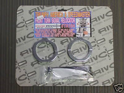
FRONT TURN SIGNAL RELOCATORS
FOR TRIUMPH AMERICA & SPEEDMASTER
#TA104 fits thru 2006 & TA104-70 fits 2007 & Newer
1. Remove the front turn signals as follows. The turn signal wire plugs are located inside the
handlebar switch housings. Remove the two Phillips screws located on the forward facing side of
the switch housing, remove the covers, unplug the turn signals and reassemble the switch
housings. Unbolt the signals from their black mounting brackets, remove the brackets from the
bottom side of the switch housings, reinstall the nuts and tighten securely.
2. Disassemble the two halves of the turn signal mounting clamps supplied, place the M6 X 25mm
button head screws thru the hole in the side of the clamp from the inside, place the spacers
supplied over the screw threads. Screw the clamps and spacers onto the turn signals. Hold the
signal/clamp assemblies up to the front fork, position the signals so that the housing/lens seam is
vertical and straight, carefully remove the assemblies from the forks and tighten the screws
securely. Install the signal/clamps onto the forks, set to the desired height and angle and tighten
the clamp screws securely.
3. Using a sharp knife slit the black wire loom from the turn signal plug back 7â€. Pull the turn signal
wires and plugs out from the loom. Fold the wires along the loom going down towards the
headlight. Leave 2-3†of the wire next to the plug exposed and neatly tape the rest of the wire to
the loom and the loom closed back up to the handlebar switch.
4. Connect the signal wires to the plugs from the wire loom. Using the cable ties supplied tie up any
loose or unconcealed wire and the plugs.
RIVCO Products, Inc
440 S. Pine St.
Burlington, WI. 53105
Ph. 262-763-8222
Blowing gravel off rural roads
|
|
|
How do remove the left grip without damaging it
|
Joined: Jan 2005
Posts: 18,825
"Lighten up, Francis."
|
|
"Lighten up, Francis."
Joined: Jan 2005
Posts: 18,825 |
From Nomad: Quote:
Easiest way with no damage to the grips should you ever want to use them again. Remove the bar end weights, work a thin bladed flat screwdriver between the inner edge of the grip and the bar, spray WD 40 through the plastic straw that comes attached to the can into the gap alongside the screwdriver blade. Work the blade around the inner side of the grip and the WD 40 will disolve the grip glue and enable you to slide it off the bar in one undamaged piece.
Original post.
|
|
|
Re: DIY Motorcycle Ramp
|
Joined: Jan 2005
Posts: 11,120 Likes: 11
Should be Riding
|
|
Should be Riding
Joined: Jan 2005
Posts: 11,120 Likes: 11 |
|
|
|
Re: Zumo Route management
|
Joined: Jan 2005
Posts: 11,120 Likes: 11
Should be Riding
|
|
Should be Riding
Joined: Jan 2005
Posts: 11,120 Likes: 11 |
Garmin Zumo 450. (discontinued model) Most of this is applicable to Garmin Models: Nuvi and Zumo. Once you have created a route using mapsource (or google maps converted to gpx, saved as a txt file then renamed with a gpx file extension), AND imported them using the Garmin import feature, you may well want to have a backup that can be re-imported at will. Place the gpx route file on the SD Card. When saving the Mapsource file ensure that you have named the route within the mapsource file SOMETHING (usually the route gpx file name without the extension. Why? Route0 is a beech. Tells you nothing descriptive of the route and can be avoided by naming the route itself. Background: Routes are stored on your GPS unit and cannot be seen using a puter. And cannot be found on the optional SD card. Mapsource is the software that allows one to send routes to the Garmin GPS unit. The directory structure of the Zumo where you can archive routes is I:\Garmin\GPX where 'I' is whatever your puter assigns to the unit after you hook up the usb cable. The directory structure of the optional installed SD card where the archive routes are stored is J:\Garmin\GPX, again, 'J' is whatever your puter assigns to the SD card after you hook the usb cable up. gpx file extensions are what most users use to convert google maps to garmin recognizable files. GMapToGPX. Click on the link and read it. Now that you have routes converted to gpx format you can perform at least two functions with them. 1. Open them with Mapsource. Then after tweaking the route(s), use mapsource to send the route to the Garmin Unit. You will not be able to find this tweaked gpx file on your Garmin Unit. (well sort of as TEMP.gpx exist – see links below) Mapsource defaults its file save function with a file extension of 'gdp'. And not to the Garmin Unit but to your harddrive or other media. Thus if you want to save the gpx file as a route archive, use Mapsource to ‘Save as’ a gpx file and save it to the SD card’s proper directory. (see above). If your route is available on the garmin unit via the ‘Where_to’ button then the ‘Route’ button, you do not and should not import this route again, should your garmin unit ask you (redundant duplicate memory intensive ). 2. Save the gpx file directly to either your Garmin Unit or the SD card. Then the unit will either prompt you that new items are available for import or you can walk the menu choices on your unit to manually import the routes. Routes: However you do it, once your routes are loaded onto Garmin using either the import function or the send function (from Mapsource), then import, they are available for use. The gpx files ARE NOT ROUTES that you will find on the 'Route Button'. The gpx files are, in essence, archived routes that need the Garmin unit to transcribe them for use via the import function. Archived/saving gpx files to the Garmin unit directory (see above) and to the SD card can cause confusion. Doing so shows at least two of each gpx route available for import. (one on the unit, one on the card). Links: Download Garmin MapSource for Free and Install Without Media Garmin's Zumo - FAQ Mapsource Tips. When you do a google maps gpx export lots of way points are created that are unnecessary. Delete as many as you can without altering the route. Tweak it so to say. If your google map has ‘stop here’ points then the gpx export will have a route for every tangit set of way points. Three way points in google maps? Then two routes. Likewise four way points then three routes. Grrr. Use Mapsource to place ‘stop here’ points, i,e, way points other wise you will get multiple routes that are a PITA. Deleting way points? Well place the pointer over the way point and if you don’t see Remove waypoint from route, select ‘cut†This deletes the whole route. Then immediately click the undo button. Now go back to the waypoint you want to delete. Right click and now you will see the choice you want! What’s up with that? Thanks Garmin. Great feature. (sarcasm) In summary. Create a route using google maps. Do a gpx conversion. Save the gibberish generated as a txt file. Rename the txt file to have a gpx extension. Open file with Mapsource. Tweak the route. Save it as a gpx file to your SD card. Import it from within the Garmin GPS realm. You will have a route available for selection and also have the raw gpx route on your SD card. Should the garmin unit burp and loose the internal route(s) you have your SD gpx to re-import all over again. More Notes: August 10th 2010Routes. The Zumo 450 has a tendency to lose and/or merge routes with similar names. Having routes loaded into the Zumo memory requires long backup times when going into Mass storage mood. To work around these issues, keep the gmx files on your SD card. Keep 'loaded' routes, i.e., those routes that are available from the 'route' button, to a minimum. This yields lower backup times and thwarts route loss or merges. Similiar route names are touchy. For example having two routes named 1. Lake Marion loop 2. Lake Marion loop North of I95 caused the first route to be lost. Not really lost as the route is available from the 'where to', 'route' buttons, but the route loaded was the 'north of I95 route. grrr Simply deleting both routes from the GPS unit memory then reloading (re-importing) the gpx file from the SD card will reload the route again, keeping the name and waypoints true to your intentions. When traveling long routes (1000 miles+) it is best to break up the routes into lengths that are ride'able in one day. Benefits include lower load times and quicker 'detour' recalculations. Keeping backup copies of the routes in gpx format on an SD card is priceless. You will never lose a route as you can re-import the route using the gpx backups. Circular routesDepending on which side you are on the GPS will calculate the route. Thus if you have a clockwise route that starts and ends at the 6 o'clock position, and you are at the 3 o'clock side, the GPS will calculate the route from that point to the end. To work around this, navigate to a point on the route that is on the other side, meaning past 6 o'clock, then reselect the route. Circular routes that overlap for periods of time are a toss up. Adding waypoints to active routesThe parameters of navigation allow you select items to avoid. Having set the unit to avoid dirt roads, the unit will not avoid dirt roads if you touch the screen, then select a point on a road along your current route, and add it as a waypoint instead of a destination. Why would one do this? To fine tune a route for more exotic roads. Just because your route takes you along a predetermined road doesn't mean you can't look at the route in detail as you travel and seeing a parallel road dropping a waypoint along it. The caveat is the road may be dirt. If it is, either ignore the altered route or cancel the route then call it up again.
Last edited by moe; 08/10/2010 3:57 PM.
Blowing gravel off rural roads
|
|
|
Ronz32 Front Turn Signal Bracket Plans
|
Joined: Jan 2005
Posts: 18,825
"Lighten up, Francis."
|
|
"Lighten up, Francis."
Joined: Jan 2005
Posts: 18,825 |
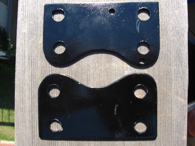
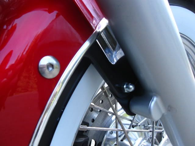
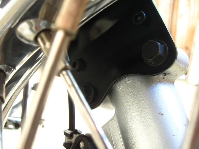
About a million years ago I made up these brackets to move the indicators off the bars, where they dangled like a pair of fluorescent scrotums, and down onto the forks where they belong. I saw the ludicrous prices folks wanted for shiny geegaws to do the same thing and, being a proper Scot, I wasn't about to shell out for something I didn't like the look of anyway. Anyhoo, here's the bracket pre-fitting: 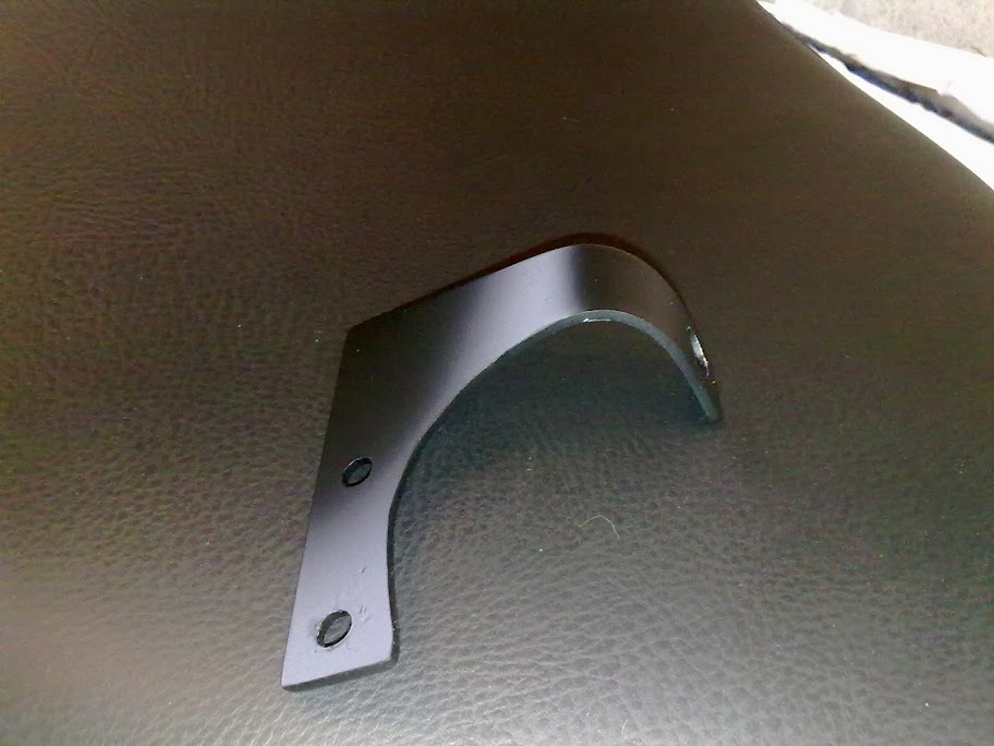 I drilled them so they would make use of the existing shroud mount holes under the bottom yoke (Yoke, not triple tree, it doesn't even look like a tree, triple or otherwise, FFS) as can be seen here. BTW There's over a year between these photos and it was winter when I took the second one, hence all the filth. I prefer riding to cleaning.  Ignore these horrible wee flashers, I was just making sure I made the holes in the brackets big enough to accept aftermarket indys if I wanted to change them. I actually ended up fitting the originals with about a 20mm spacer to let them peep out from behind the forks. I used 2mm stainless to make them and gave them a couple of coats of matt black, which you can see flaking off in the second shot in the last post: 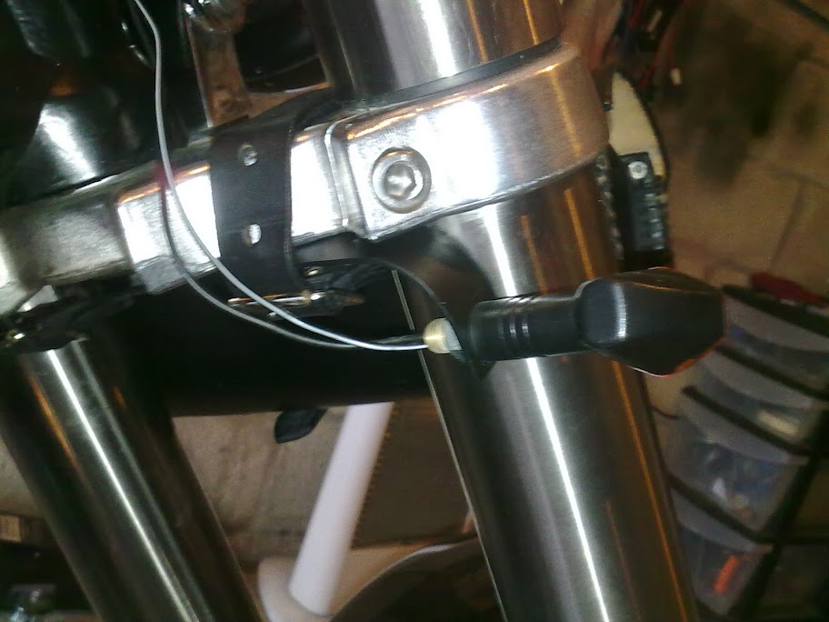 The plans and dimensions in PDF The plans and dimensions in PDF
|
|
|
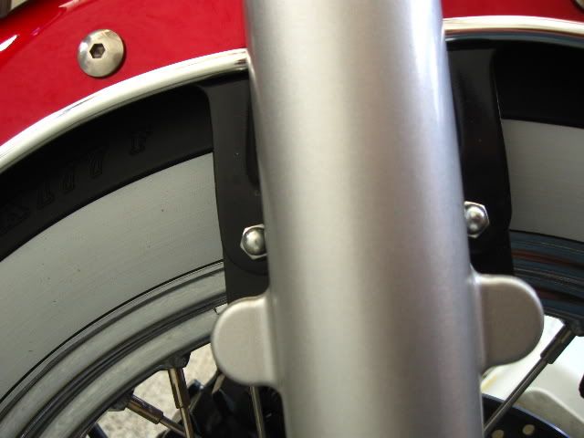
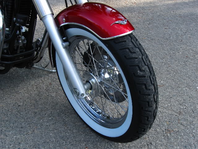
Front Fender Extension for 120 series tires
|
Joined: Jan 2005
Posts: 18,825
"Lighten up, Francis."
|
|
"Lighten up, Francis."
Joined: Jan 2005
Posts: 18,825 |
|
|
|
Friar's Lightbar Bracket Pics and Plans and Notes
|
Joined: Jan 2005
Posts: 18,825
"Lighten up, Francis."
|
|
"Lighten up, Francis."
Joined: Jan 2005
Posts: 18,825 |
Turns out there wasn't enough interest to do a run of these, so I'm dumping the info here. Keep in mind the following license:  Friar's Lightbar Friar's Lightbar by John Bedard is licensed under a Creative Commons Attribution-NonCommercial 3.0 Unported License. Based on a work at lh5.googleusercontent.com. With that out of the way, here are pictures of the original I made from flat steel and had chromed several years ago: 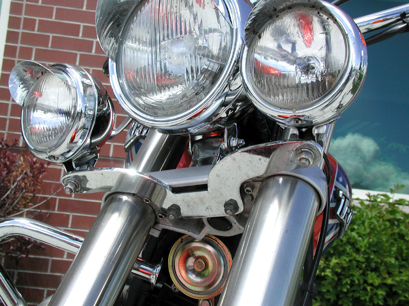 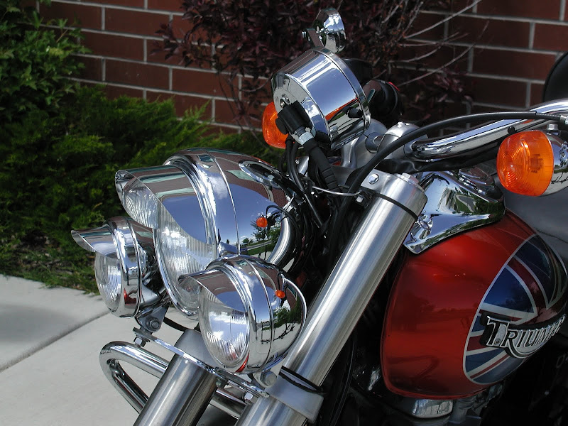 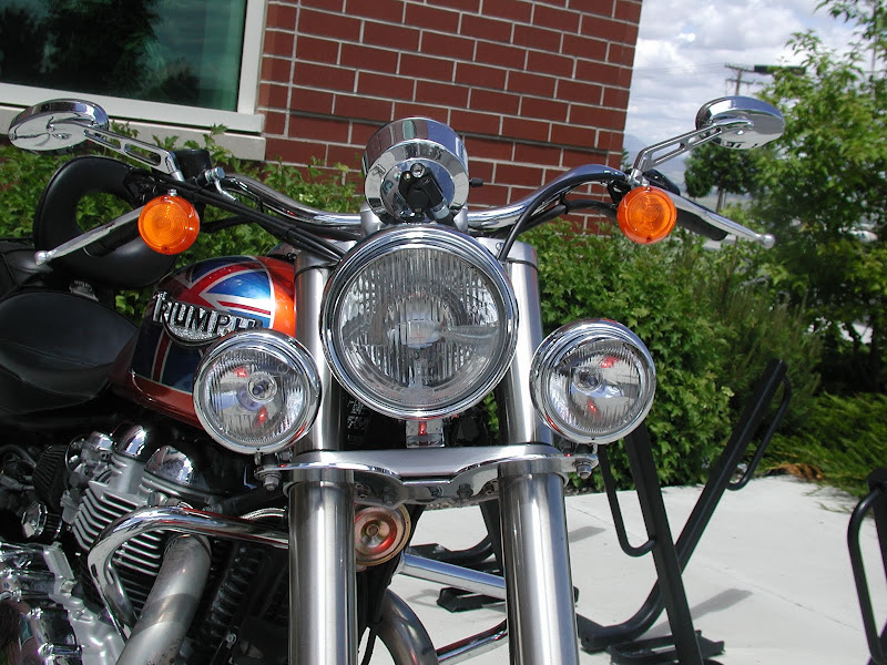 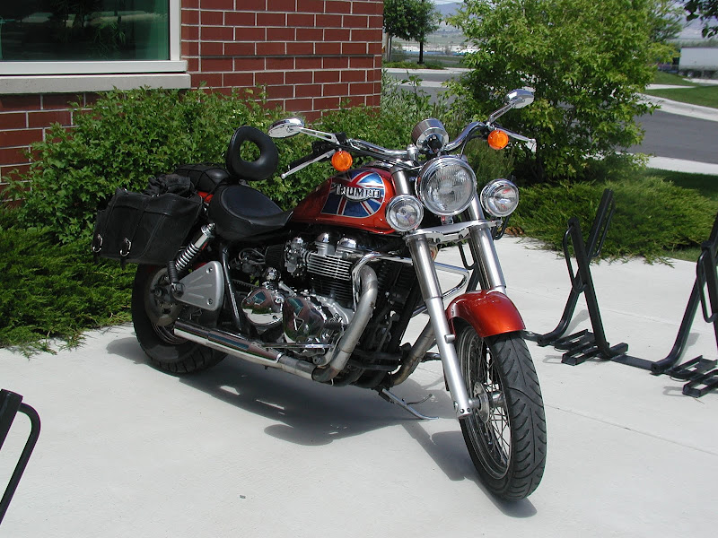 Here's the file I sent to the waterjet cutter for the first prototype. For you do-it-yourselfers, have at it, I only ask you don't redistribute this image without attribution and a link to this thread, and certainly don't use it to make any money. You don't need to use a waterjet, if you have the know-how you can just print the larger one out and transfer it to metal and start cutting.  Larger Image Larger Image Trial fit of the prototype. Just put a bolt in to locate the bracket. Looks good to me. I added an 1/8" to the center portion to close up the gap towards the front of the yoke. Not to bring it flush, necessarily, just close the gap. NOTE: The image above doesn't have the extra added to the center section, which should be 2" deep, not 1-7/8". I'll track down the latest image and fix this post later.  Here you can see the gap I'm referring to, as well as the potential interference with the two front fork shroud bolts.  Clears the fork shroud area itself.  Sticks out plenty far so the lights won't interfere with anything else.  Just about any lights will work, provided they have a pivoting base (Bates-style mount?). My original bracket was a direct replacement for the bar that comes with the factory lightbar kit. You could use cheap fog lights, PIAA driving lights or Joker Machine halogens or whatever, just remember the base has to pivot like the factory lights. As far as the wiring goes, I recommend buying the original factory lightbar wiring harness. It's around $30 and it's plug and play. Potential lights, ranging from inexpensive to top of the line: http://www.fasteddysports.com/?page_id=3&product_id=603http://www.fasteddysports.com/?page_id=3&product_id=602http://www.jokermachine.com/itemstreet2004.asp?ItemID=419&CategoryID=70&Placeholder=0Now go forth and cut metal...
|
|
|
Re: Pingel Installation instuctions
|
Joined: Jan 2005
Posts: 11,120 Likes: 11
Should be Riding
|
|
Should be Riding
Joined: Jan 2005
Posts: 11,120 Likes: 11 |
Thanks to Mike at BellaCorse for clearing up the installation issues vis-a-vis the supplied gasket and sealant. -The Pingel petcock I sell does not require any drilling, filing or and other modifications. It's a simple bolt-on install. -Pingel claims 30% more gpm flow rate than the stock Mikuni petcock. Now, as to how that relates to power, I'd say that there is no real tangable performance gains with a stock engine, carbs etc. If you've spent the megabucks on FCR's, big bore kits, camshafts and pod filters, then's what's another C-note? -Increasing the size of the Pingel to 3/8"NTP gains you absolutely nothing, performance wise. If you want skulls & flames milled into the sides, then you're covered.<sic> This larger size DOES require opening up the fuel tank opening by drilling or filing. Clean that tank thoroughly!!! -The ergonomics of Pingel's smooth acting horizontally swinging lever is far more intuitive than the rotary dial on the stock petcock (IHMO). All the way forward is Off. All the way back is On. 1/2 between the two is reserve. How many of you ran low on fuel only to reach for your petcock and NOT remember if reserve is 9:00 position, or 12:00? -The stock Mikuni petcocks are prone to failure. I base this comment on the feedback I get from my customers who are replacing them for no other reason than failure. -The stock Mikuni petcock is not rebuildable. -The paper gasket provided with the Pingel has been a source of problems with some customers. The sealant that Pingel provides seems to dissolve the paper UNLESS you allow it to tack-up first. Installing a fully wet paper gasket on both sides will cause to to tear once the base plate is tightened. The proper technique -(IMHO)- is to apply a very thin coat of sealant to the gas tank surface and allow it to almost completely dry (still sticky to the touch, but not runny). Apply a thin coat of sealant to ONE SIDE of the paper gasket and allow it to almost dry, but still tacky. At this point, you can install the base plate with the sticky side of the paper gasket facing the fuel tank. There is no sealant used between the base plate and the gasket. This is important should you ever need to remove the petcock. Tighten the two Allenhead screws lightly and allow the sealant to fully dry in a couple of hours. Then you can tighten the screws to the required torque and thread-on the petcock using a wrap or two of teflon tape. -Do not overtighten the petcock as you can crack the threads if you go too far. A couple of exposed threads is perfectly fine. Use common sense (HA... that's laughable). So there you have it. I'm the first one to tell you that if your stock petcock is working OK and you're fine with it's operation, then there is no reason to replace it. If you are having some petcock issues and/or you want to add some practical bling, them the Pingel is by far-and-away, a great item to have. Mike
Blowing gravel off rural roads
|
|
|
Dual Headlights, beeyotches
|
Joined: Jan 2005
Posts: 18,825
"Lighten up, Francis."
|
|
"Lighten up, Francis."
Joined: Jan 2005
Posts: 18,825 |
From Jesterminute: http://www.bonnevilleamerica.com/forums/showthreaded.php?Cat=0&Number=553905&page=0&vc=1  I think there's a rough draft of the bracket I made for mine here also. It's a little out (i use washers) but it's a straight bolt on and replace once you've got it right. 
Last edited by FriarJohn; 03/27/2012 5:45 PM.
|
|
|
Re: How To's - Replacing Neutral Switch
|
Joined: Jan 2005
Posts: 11,120 Likes: 11
Should be Riding
|
|
Should be Riding
Joined: Jan 2005
Posts: 11,120 Likes: 11 |
Neutral Safety Switch Triumph part number: T1190014 Bike Bandit Part Number: 1387721 New Neutral Switch Installed - followup with pics Thread's first post, Authored by and courtesy of Gary Storms ( Blue05Speedmaster) Quote:
Replaced the Neutral Switch (dealer $24.00 plus crush washer) today and have pictures here as promised. Hope they show up or else I will need help getting them to show.
The switch was leaking from the electrical connection end. It also showed signs of wear on the pin end were it touches the slider inside the transmission. This is after 20,980 miles. I changed my oil at the same time and it was already drained when I removed the switch so no oil came out of the switch port in the transmission.
New and old (left side) switches

Neutral switch port in upper right . large port is where the oil filter attaches.

This shows the pin wear (one on left side)
I suspect that others with similar mileage would have similar wear which in my opinion is significant.

FYI - Great Nm torque wrench for this small size stuff

Hope they are here and hope this helps others with similar problem _OIL LEAK TO REAR OF OIL FILTER
Gary
Last edited by moe; 12/03/2012 3:22 PM.
Blowing gravel off rural roads
|
|
|
Re: How To's - Fork disassembly
|
Joined: Jan 2005
Posts: 4,056 Likes: 78
Loquacious
|
|
Loquacious
Joined: Jan 2005
Posts: 4,056 Likes: 78 |
Thanks to Zmilin... Ive done this a few times and finally decided to document the process for disassembly of the forks. I made a video and will include the link here as well as some pics for reference. Video = Fork disassembly videoSorry about the poor lighting... my lighting crew was off today  Cap, spacer, washer, spring into fork tube...  Damper rod bolt and washer  Dust cap & Snap ring removal 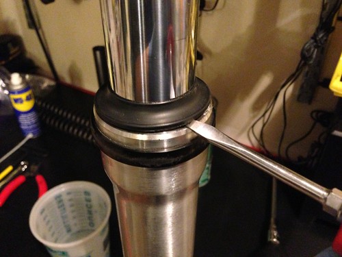  Damper rod and rebound spring under fork spring 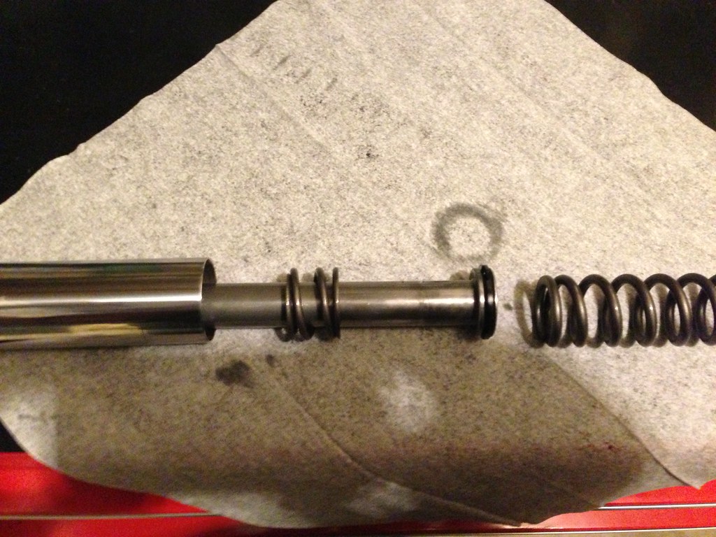 Damper rod assembly and damper rod seat (oil seal, washer and bushing still on fork tube) 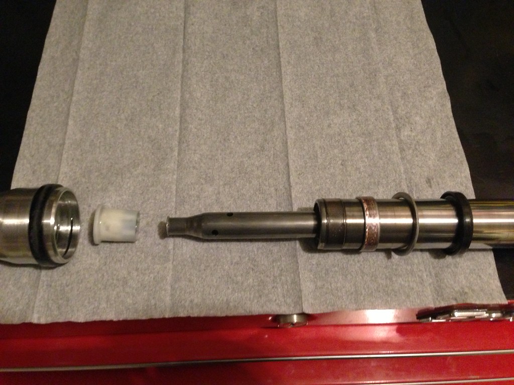 Damper rod and rebound spring 
|
|
|
Re: Kury Flush Mount Gas Cap
|
Joined: Jan 2005
Posts: 11,120 Likes: 11
Should be Riding
|
|
Should be Riding
Joined: Jan 2005
Posts: 11,120 Likes: 11 |
Blowing gravel off rural roads
|
|
|
|
|


