Gleaned from varoius post, this thread tosses out some voltage readings at the battery, then goes on to walk us through testing the Alternator/stator/rotor (you choose the term...)
From
oldroadie  Keith
Keith's burned out one
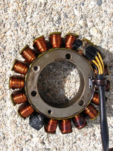
btw kudos to Keith for his work in lighting our path to yota...or is that yogi?
And the regulator
no picture...

Voltage Readings at Battery
Grzegorz’s reading:
On the idle at 1000rpm should be at least 14 V
Gmike’s readings:
Off 12.85
Idle 1000 RPM 13.10
3000 RPM 14.05
From
Chy:
Alright, a little basic info from my Haynes manual.
It says 12.5 volts at idle and 14.5 at 4000 rpm's. Voltage at the Alternator connector at 4000 rpm's should be 60 or 70 volts ac... if "much less" check the alternator.
It goes on to say that there are no checks for the Regulator/rectifier, if possible replace it with a known good one.
No real specs on the alternator windings except that they should be a "low" resistance reading between all terminals and that none should have continuity to ground.
That's pretty much it for Mr Haynes.. hope some of it helps.
Before you do anything else, check your fuse panel. Fuse no 11 might be burnt. The regulator feeds the battery through that circuit. Check your other fuses while you are at it.
From
midnight7503:
I take it the 03 models have the wiring running under the carbs?
my 06 runs down under the motor, so only slightly different
trace the wires from the cover of the rotor (alternator) to the joiner before the regulator, run a multi meter across the 3 wires in turn pairing them up, on the rotor side, start the motor and rev to around 4000rpm and and note the readings, this is where you should get a reading of between 60-70 volts, if its lower then you know where your problem is, if it is between that, then it may be your regulator.
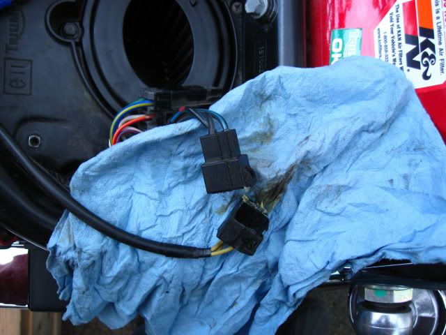
EDITOR: Look under your saddle for the connector or joiner as
midnight7503 calls it. The photo below is of
Keith's joiner/connector.
 Decosse:
Before you start it:
First, that connector above is the one I wanted you to inspect to look for any signs of burning/damage
(also - how did the connector the R/R plugged into look?)
Next, at same connector, do the test I outlined parenthetically below - measure the resistance between any of the three pins (does not matter which one) to engine ground - should be 'open' i.e. infinite resistance.
(unplug the stator and measure resistance between any one of the three terminals in the connector [end that goes back to the stator, NOT the R/R] and engine ground - that should be open circuit, infinite resistance.
If you measure short (zero ohms) then your stator is 100% to be bad.
Conversely, if 'open', not absolute guarantee is good, but high probabilty it is OK. )
If that is good (i.e. not short) then you can start it;
with meter on AC Volts measure from pins 1-2, 2-3 and 3-1 in turn (doesn't matter which you call 1 etc)
All three should the same at any given rpm - at idle expect ~ 20V. As you increase rpm the voltage should rise, but again, if you fix the rpm (say 4000 rpm), all three should be the same - the absolute numbers are less important, that they are balanced is what indicates one leg is not 'down'.
Again, if you get a 'short' in the first (resistance)test, don't even bother starting it.

LINKS
Electrical charging issues... Electrical blues HELP! getting a charge out of your BA/Speedy Re: Weak charging system? - the solution